Photogrammetry: from a Simple Image to a 3D Measuring Report
Photogrammetry: from a Simple Image to a 3D Measuring Report
Photogrammetry is a non-contact measurement method that is used in industrial quality assurance and component development, among other things.
How does photogrammetry work?
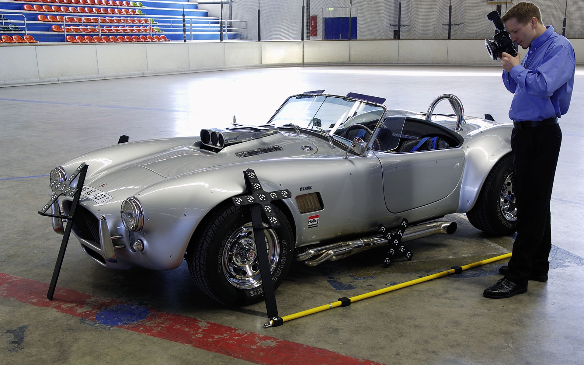
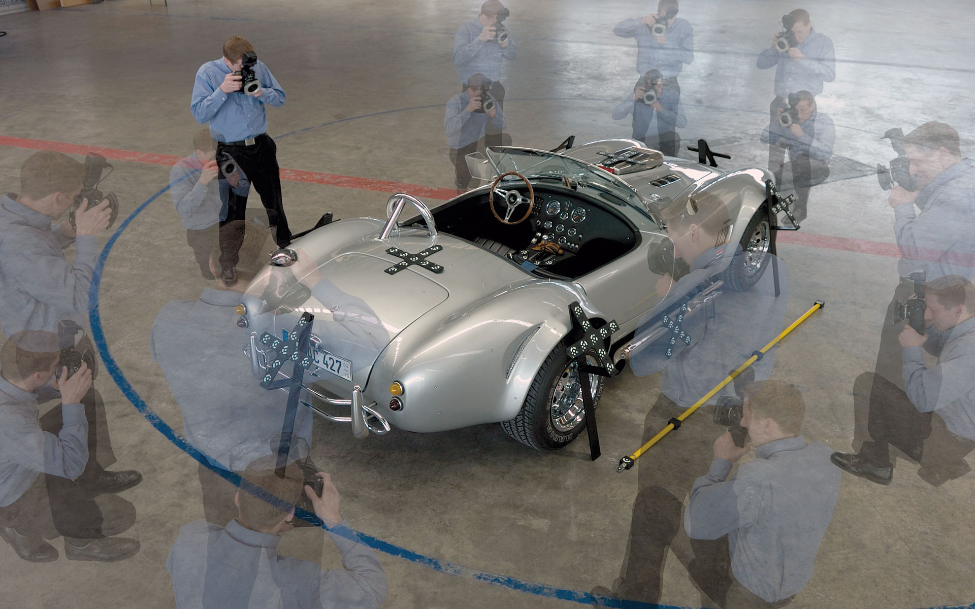
Prior to the measurement, coded and uncoded reference points are placed on the measuring object and scale bars are positioned in the measurement environment to achieve highly accurate measurement results. Then, the object to be measured is captured from different perspectives with a digital measuring camera—this is done manually or using a robot.
The photographic images are then transferred to an inspection software for further processing: Based on mathematical curve fitting, the software generates a precise model. Relevant factors such as camera positions, ray intersections, lens distortions and object coordinates are taken into account for this. The user gets 3D coordinates for each reference point as a 3D point cloud.
The 3D point cloud can then be used for different metrological analyses, such as nominal-actual comparisons (for example, against CAD) and GD&T checks. Furthermore, the photogrammetry software can compute three-dimensional translations (6DoF) and deformations of points and entire components in many different load conditions.
Photogrammetric basics
Various preconditions must be met in order for the coordinates of an object to be reliably determined. The imaging geometry of the camera as the inner orientation must be known. This is determined by the camera parameters consisting of image constant, coordinates of the principal point and lens distortions. The required knowledge about the outer orientation results from the camera position in the global coordinate system. It describes the exact position and orientation of the camera. By taking several images of many points from different directions, different equations can be set up to determine all unknowns (inner orientation, outer orientation, position of the measurement targets). This process is called bundle adjustment (alternative name: bundle block adjustment).
Computation of 3D coordinates of the measuring object

What is the difference between photogrammetry and 3D scanning?
In 3D scanning, the measuring object is digitized over its entire surface. The user gets information on the whole surface of the object. In photogrammetry, however, only 3D coordinates are captured—thus, the object is represented based on points. This is the reason why photogrammetry systems are often called mobile 3D coordinate measuring machines (CMM).
Advantages of photogrammetry systems compared to scanning systems
With photogrammetry systems, measurement data is acquired wirelessly using a digital measuring camera. This is particularly advantageous for very large measuring objects: The user can move freely around the entire object and reach every corner.
Another advantage of photogrammetry: It can cope with all lighting conditions—from bright sunlight to darkness—and can therefore also be used outside of enclosed spaces. Other measurement methods are much more demanding with regard to tolerable lighting conditions and fail, among other things, when the sun dazzles.
Third advantage: Photogrammetry systems are very compact so that the user can transport them in a handy suitcase to the measuring object. This way, the photogrammetry system can be very flexibly used at many different locations around the world for any measuring object.
Usual application fields of photogrammetry in the industrial sector
Generally, photogrammetry is used if measuring with scanning systems would be very time-consuming. This is often the case with measurements of very large objects under harsh ambient conditions. Typical application fields are shipbuilding, the wind energy sector (also called offshore) and aerospace.
A concrete example from practice: Because of their large size, wind turbines are transported in individual parts to their offshore setup destination. To guarantee a smooth setup of the offshore wind turbines, using a photogrammetry measuring system for checking the mounting surfaces and bolts is recommended—at the manufacturing site and also offshore: If the position of the bolts in the foundation of the wind turbines is checked at the factory before delivery, necessary corrections can be made immediately if deviations to nominal were detected. After anchoring the foundation at the setup destination, a second photogrammetric measurement offshore can check again whether the mounting bolts fit to the hole pattern of the tower segment to be mounted. This way, high additional costs and time-consuming extra work can be avoided when installing the wind turbines. Due to the simple measuring process, the inspection of over 120 mounting bolts can be accomplished by a single person.
In addition, photogrammetry systems are ideally suited for measurement data acquisition during kinematic and thermal load testing in climate chambers, for example, for component tests in the automotive industry: They generate precise measurement results even at extreme temperatures and provide information about deformations on the measuring object.
GOM’s industrial photogrammetry system
GOM offers two photogrammetric solutions for industrial applications: TRITOP and ATOS Plus.
TRITOP
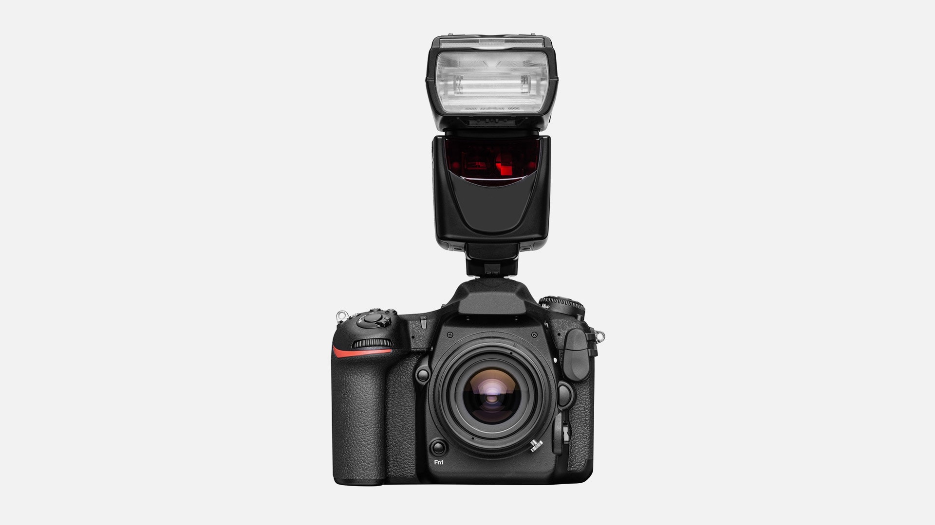
The TRITOP photogrammetry system is an optical 3D coordinate system that can be easily carried. It measures even large objects (2–10 m or larger) precisely. The high-resolution images captured by the digital measuring camera are transferred to the connected software and evaluated. For example, polygon meshes from point clouds can be created, 3D inspections can be performed and the measurement results can be compared against imported CAD data. The measurement results are summarized clearly in a measuring report.
Manually guided ATOS scanners can be complemented by a TRITOP system for measuring reference points.
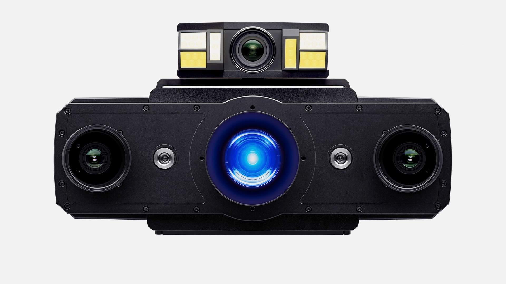
ATOS Plus
ATOS Plus fulfills another purpose: It is a photogrammetic add-on sensor for ATOS 3D scanners guided by robots. This sensor conducts the measurement of the reference points and increases the overall measuring accuracy. For this purpose, ATOS Plus is mounted directly on the ATOS 3D scanner. The sensor captures the photogrammetric reference point markers fully automatically. These reference point markers provide a global coordinate system in which the single measurements created by the scanner are transformed automatically.