Triangulation: proven measuring principle with a future
Accuracy and reliable results have the highest priority in metrology. This is the only way to guarantee that components meet both quality and safety standards. Triangulation, i.e. distance measurement by calculating angles on the basis of triangles, is a measuring method that can be used to record the surfaces of objects. On this page you will learn how triangulation is used in metrology and what structured light projection and the light section method are all about.
The Triangulation Method Briefly Explained
In metrology, the triangulation method is used to measure objects with the aid of individual laser points and lines or, as in the picture above, with entire light patterns. One or more cameras with sensors record the angle at which the light is reflected from the object, or the light patterns are deformed on the surface, as well as brightness and distance. In this way, light irradiation and angle measurement produce a comprehensive overall image of the surface of the measured object.
Triangulation was already used in Europe and America in the 17th century, but for land surveying. That is where the principle originated. When surveying with triangulation, an area is divided into triangles to measure the distance. For triangles, it is enough to know the angles and a baseline to easily calculate the missing lengths by trigonometry.
Nowadays, the triangulation principle is used far beyond land surveying, e.g. in photogrammetry or 3D scanning. In metrology, triangulation is mainly used to inspect components. There are two different triangulation methods for this purpose:
- Structured light projection (fringe projection)
- Laser triangulation (triangulation using light-sectioning methods)
Laser triangulation works with a single laser dot or line that is reflected from the measured object and then detected by sensors. In the principle of structured light projection, a large light pattern is projected onto the object to be measured. One or more cameras with sensors capture the shape of the light pattern, which is deformed on the surface of the object.
Both methods are frequently used in metrology; depending on the measurement task, one or the other measurement principle is more suitable. Dive deeper into 3D triangulation with laser and fringe projection and find the right method for your project.
How does the structured light projection work?
In triangulation with fringe projection, different light patterns in the form of fringes or points are projected one after the other onto a test object in order to map the exact shape in a 3D model. To do this, a projector and next to it at least one camera with sensors, but usually two, are pointed at a flat surface. The cameras know the distance between themselves and the surface as well as the angle at which the light pattern is projected onto the object. To start the measurement with the structured light projection, the test object is placed on the surface. The light patterns are projected onto the object and deform based on the surface shape. These altered point or fringe patterns are detected by the cameras, providing the information needed to calculate the distance from each point on the surface in the field of view. This results in what is known as a point cloud (STL mesh), i.e. an accurate image of the measured object made up of many small measuring points.
The light used for scanning with fringe projection can be blue or white. Mostly, however, blue light is used to reduce diffraction and ambient light influences on the measurement. The surface on which the target is placed is usually black to avoid light reflections.

What Can the Fringe Projection Method be Used for?
Due to the high scanning speed, especially with simultaneous acquisition of many measurements, structured light projection is very well suited for industrial inspection tasks, such as:
- Form, position and contour control
- Area comparison, target/actual comparison
- Completeness
- Position of components in assemblies
- Cut positioning
The principle of structured light projection is also frequently used in forensics, as it is suitable for even the smallest objects. Fringe projection is rather unsuitable for transparent or strongly reflecting objects to be measured.
Advantages and disadvantages of structured light projection
Advantages of structured light projection:
- Areal 3D information with constant resolution
- High measuring point density
- High measuring speed
- Flexible and portable measurement setup
Disadvantages of structured light projection
- Higher demands on projection technology
- Translucent or reflective surfaces may require pre-treatment
- Ambient light can influence measurements
- Rough surfaces make distance measurement with a laser dot difficult (laser lines are not affected)
How Does Triangulation Work with the Light Section Method?
The setup for a measurement with the light section method, which is also based on triangulation, is similar to that of structured light projection. A measurement object is placed on a flat surface, usually a turntable, and a projector and camera or sensor are placed above it. These three points form the triangulation triangle, which can be used to perform the calculations. However, compared to fringe projection, where a pattern of fringes or dots is projected onto the target, triangulation with a laser uses only a single laser dot or line. The decisive factor here is also not the direct deformation of the light on the surface, but the reflection of the light. The surface of the measured object reflects the projected laser line or point in the direction of the camera. The camera detects the reflection and calculates the distance from each point in the field of view based on the angle of reflection.
Since the laser line or dot captures only a portion of the object and not the entire surface in one scan as with structured light projection, either the measurement object or the sensors must be moved. A stable measurement installation is therefore essential for triangulation with the light section method to ensure high accuracy of the measurement.
What can Laser Triangulation be Used for?
With the measuring principle of laser triangulation, very precise measurements can be made in the smallest micrometer ranges. But even larger distances are no problem with the light section method of triangulation. Therefore, this triangulation method is a popular measurement method in industrial manufacturing processes. It can be used for quality control, profile and contour measurement as well as for determining material thickness, vibrations and distances. With laser optical triangulation, defective objects can be detected early and removed from manufacturing processes for repair or recycling. For shiny metals, measurement with laser triangulation is usually better than with fringe projection. Reflection could provide erroneous signals in the measurement principle with fringe patterns, whereas the method with laser works with exactly this reflection. Surfaces that are too shiny can still cause problems when measuring with triangulation. The principle of laser triangulation is also frequently used in the packaging and wood industries, logistics, medical technology and electronics production.
Laser triangulation works with blue or red laser light. The red light penetrates the target, whereas the blue laser forms a sharp point or line on the surface. In addition, the blue laser can provide accurate results on glowing objects, while red sensors are irritated by the red glowing metals and provide false signals. For dark surfaces, the red lasers can show their advantage as they provide higher light intensity. Rough surfaces are also measured with red laser using triangulation, blue light is more suitable for smooth surfaces.
Advantages and Disadvantages of 3D Laser Scanning
Advantages of laser scanners:
- Independent of ambient light conditions
- High accuracy of measurements
- High measuring speed
- Sensor head can be mounted on existing measuring systems, e.g. on a coordinate measuring machine
- Shiny metals can be measured
Disadvantages of laser scanners:
- Loss of resolution possible due to laser granulation and movement
- No process reliability, as measurements are temperature-dependent
- Highly shiny or translucent objects are difficult to measure
Highest Accuracy with the Triangulation Method with ATOS Sensors
With the ATOS triangulation sensors you can perform extremely precise measurements and obtain reliable results. Two cameras and a projector enable measurement processes with the structured light projection and light section methods.
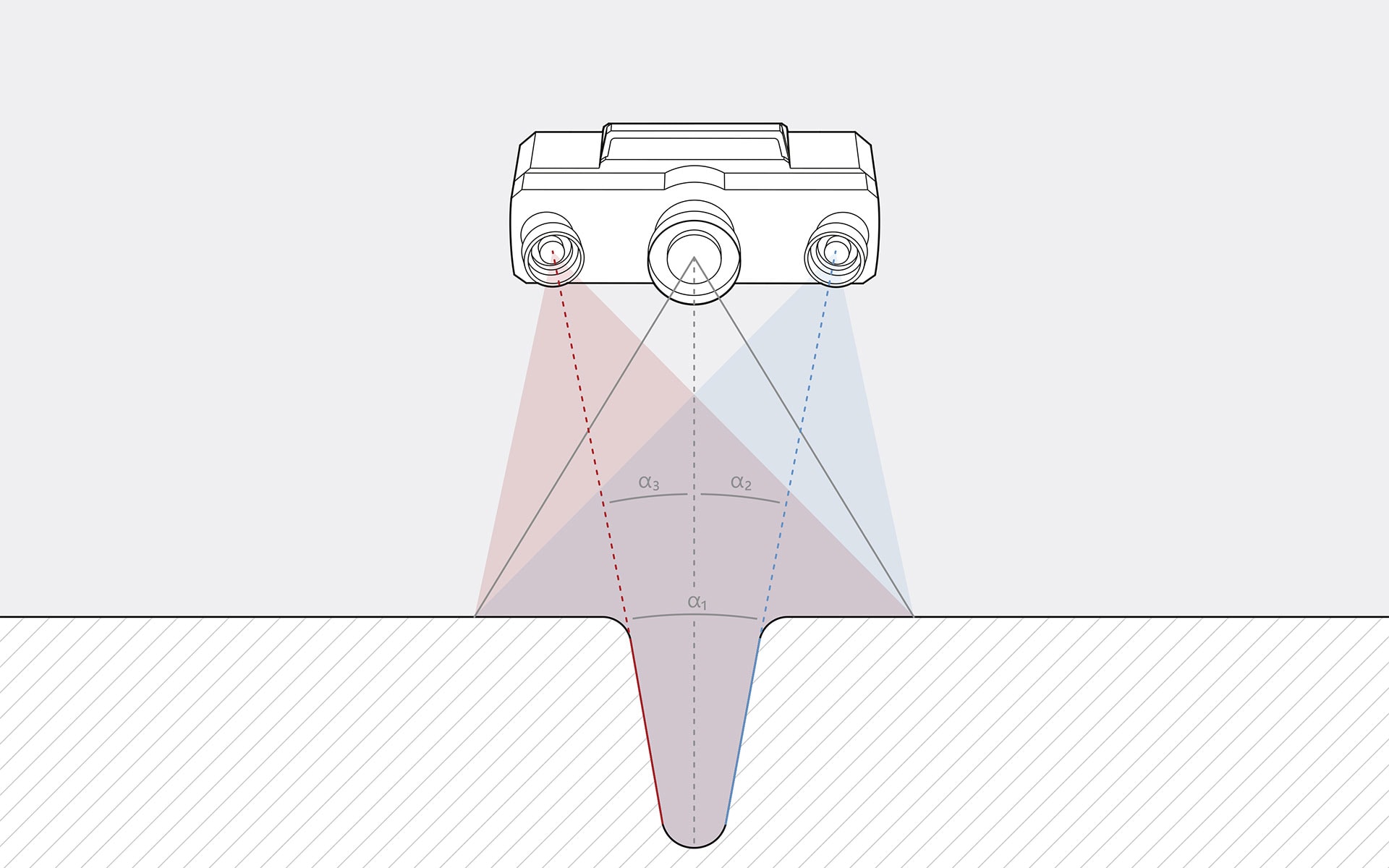
The ATOS 3D digitizers offer a very special detail: The right and left triangulation sensors can be used individually in combination with the projector. This means that three different views of the measured object can be captured with one scan. This can save a lot of time, as the number of individual scans is significantly reduced, even for complex components.
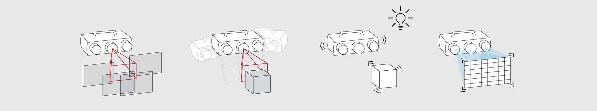
Another advantage of this triple scan method is over-determination. By capturing the component with two cameras at the same time, more information is collected than would be needed to map the 3D model. More data means higher precision. Sensor and target motion as well as environmental changes are detected, transformation accuracy is checked, and the 3D sensor position is tracked live. This allows measurements to be taken with maximum accuracy and increases process reliability. The following graphic shows the Triple Scan process with overdetermination via ATOS sensors.
In structured light projection, the ATOS triangulation sensors work with Blue Light Technology: the narrow-band blue light from the projection unit enables the scanner to take precise measurements regardless of the ambient light conditions and even shiny surfaces. Thanks to the comprehensive operation of the triangulation sensors, an accurate image of the object is created.
To take measurements with the fringe projection, a structured fringe pattern is projected onto the object to be measured. The coded fringe pattern changes rapidly during the scan and is barely visible to the human eye. This is where the functionality of the fringe light scanners comes into play. The two triangulation sensors detect the changing stripes and use them to calculate the 3D coordinates for each camera pixel using optical transformation equations. Millions of measuring points with the finest details are thus captured without contact in just a few seconds. The sensor software automatically creates a high-resolution point cloud that represents a precise image of the measurement object.
Unbeatable: Measure Complex Objects with ATOS and TRITOP
With the powerful combination of ATOS sensors and the TRITOP photogrammetric measurement system, even inspections of large and complex objects are no problem. TRITOP is used to measure reference points on the component, while ATOS uses the reference points to automatically transform the individual measurements. This results in a very high accuracy and overlapping measurements can be largely dispensed with. This unbeatable combination is especially useful for first article inspection, tool making and automotive body-in-white. You too can use the powerful combination of ATOS and TRITOP for your complex measurement processes.Flexible 3D Scanners


