Tensile Test
Tensile Test: Comprehensive Materials Testing Especially in Mechanical Engineering
Tensile tests inspect materials such as steel for their ultimate tensile strength. The standardized tensile test specimens allow conclusions to be drawn about the properties and tensile behavior of the respective materials.
What is a tensile test?
Tensile tests are standardized, quasistatic testing methods in which certain material parameters are measured. They are destructive methods, because the specimens to be tested are often loaded beyond the yield strength. Materials testing is performed by tensile testing machines and universal testing machines. The devices display one-dimensional movements in a stress-strain curve and a force-displacement curve. The determined parameters provide information on the properties and the tensile behavior of the tested materials. Which testing machine is used depends on the respective requirements. Machines range from table top systems (3 kN) to 50 kN systems equipped with a double spindle to tensile testing machines with high load capacities between 300 kN and 2000 kN.
The standards applicable to tensile testing machines are the general standard DIN 51222, DIN EN ISO 6892-1 and DIN EN ISO 7500-1 for metallic materials and ISO 5893 for plastics and rubber. DIN 50125 specifies which requirements apply to the materials of the tensile test specimen. For the failure strain, for some materials, the measurement length is used and for other materials, the proportionality factor is used. The purpose of the testing procedure is to find out, for example, what load the material can bear without plastically deforming and at what force the material is destroyed. Furthermore, the properties and the deformation behavior of hard foam, soft-elastic foam, rubber and fiber-reinforced composites are determined.
The cross section of the specimen used depends on the selected original material. If the steel has a high volume, a specimen with a round cross section is produced from the solid material. For materials testing of sheet metals, a flat tensile specimen is required (rectangular or square cross section). This testing procedure is preferably used in mechanical engineering because it also allows conclusions about other types of load.
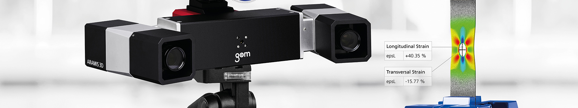
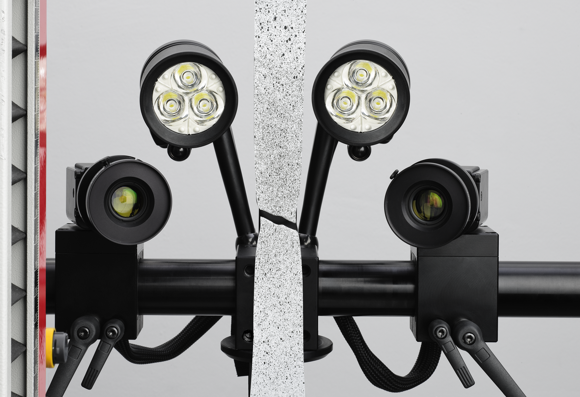
Tensile tests can be performed with touching (clip-on extensometers) and non-contact measuring systems. With clip-on extensometers, at least two blades are applied to the specimen. These measure the elongation of the artifact clamped between them. Nowadays, non-contact measuring is performed with digital, optical extensometers. The sensor positioned in the measuring device captures the elongation. Such measuring devices have the advantage that they can also precisely capture very fast strains. Some models are also suited for measuring very hot materials. These extensometers can also be used for destructive tensile tests because they have enough distance to the artifact.
Tensile test workflow
The traditional tensile test is the so-called breaking test: The standardized specimen is clamped into the testing machine and, as the tensile load increases, stretched until it breaks or tears. Only artifacts with a small cross section are used. The strain of the specimen is performed shock-free and at low velocity. During the test, the force affecting the artifact and the elongation in the measuring range are measured. The static testing machine generates a force-displacement curve and shows it on the PC monitor.
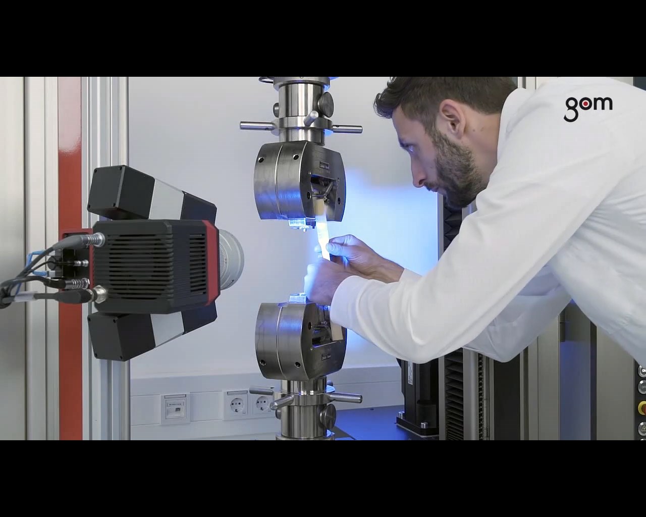
Tensile testing machines include a fixed and a movable crosshead, which is driven by one or two spindles. The drive functions hydraulically or electrically. Before the tensile test, the velocity of the crosshead is defined and the specimen is clamped between the crossheads using holders. Then, the crosshead is moved at constant velocity to one direction until the material tears. The testing device records the deformation of the specimen as well as the force required using the crosshead or an extensometer. Then, the tensile stress and strain are computed by relating the read values to the dimensions of the tensile test specimen. The tensile stress is determined from the cross section before the test. The failure strain is computed by the crosshead displacement.
In other tensile tests, parts or specimens are subjected to a tensile force until the required test load is reached. This is a nondestructive tensile test. Such materials testings are performed to ensure that the loaded part meets the technical requirements. Because further processing changes the material properties, the material must be tested again later.
Stress-strain curve
Based on the stress-strain curve generated after the tensile test, the following parameters are determined:
- Ultimate tensile strength
- Young’s modulus
- Yield strength (lower, upper)
- Yield point
- Failure strain
- Uniform strain
- Necking
Ultimate tensile strength
The tensile stress of the specimen increases continuously until no further increase in force is required to cause the elongation. Then, the specimen tears. In the course of the uniform strain of the material, necking occurs at one point of the artifact. This so-called waist formation occurs when the maximum force is exceeded. Then, the tensile stress is determined. The necking accelerates until the specimen breaks. If the artifact is a metal rod, it has so many dislocations in the crystal lattice that solidification is impossible. They contribute to the formation of cavities. Then, necking and cavities reduce the cross section of the specimen. If stress is applied to a reducing cross section, necking increases. The metal rod tears.
(Distinct) Yield strength
It is differentiated between the upper and the lower yield strength. The upper yield strength describes the point when the specimen is deformed plastically for the first time. The material fibers tear. This results in a decrease of stress and permanent elongation of the specimen. The lower yield strength describes the point after the first deformation where the decrease of the tensile stress is at the highest point. Then, the tensile stress increases continuously again. For specimens with a distinct yield strength, the stress is reduced before the break: The strain continues to increase as the material begins to yield. For materials with no distinct yield strength, such as cold-formed and cold-rolled steels, the break occurs in the ultimate tensile strength range. Materials such as unalloyed structural steel (St 37) have a distinct yield strength.
Young’s modulus
Young’s modulus describes the linear-elastic deformation behavior. If the yield strength has not been reached yet, the deformation will decrease completely if no more force is applied. The parameter is identical to the slope of Hooke’s straight line.
Yield point
The yield point is the stress value above which the specimen is permanently elongated if the yield point is exceeded. Even if no more force is applied, the tensile specimen does not go back to its original length.
Failure strain
Failure strain is the permanent strain of the artifact after the break.
Uniform strain
Uniform strain is the nonproportional strain of the tensile specimen when reaching the highest force or maximum stress.
