Reverse Engineering: Transferring a Volume Model into Design Data
Reverse Engineering: Transferring a Volume Model into Design Data
What is reverse engineering?
Reverse engineering describes the reverse design process of a part or tool and is also referred to as surface reconstruction. Unlike in the conventional development process of a part, it is not the design data that is available first, but the data is derived from the part or tool itself.
Where is reverse engineering used?
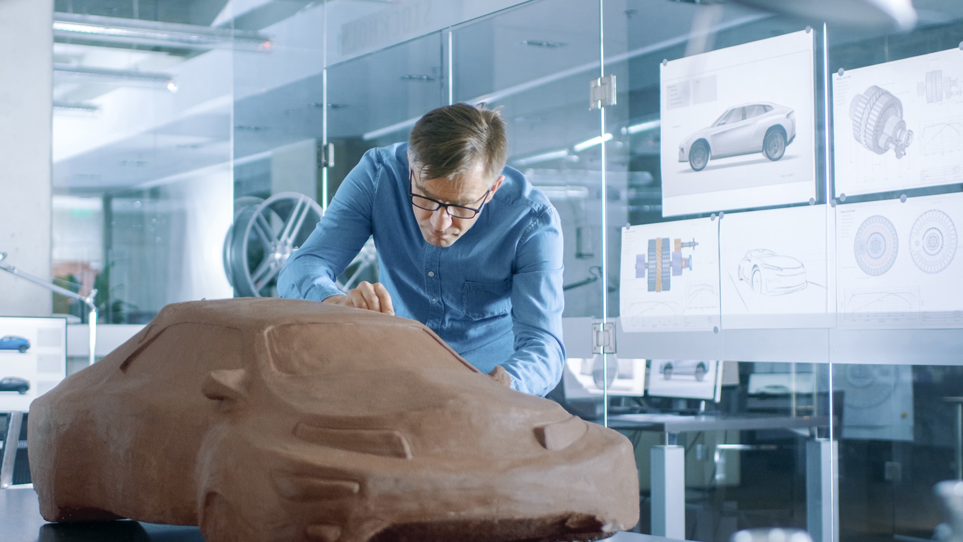
Reverse engineering is mainly used in design and product development, where handcrafted illustrative or design models and manual changes to these models are transferred into a CAD model, for example in automotive engineering or prototype construction.Another important field of application for reverse engineering is tool and mold making, where it is possible to create CAD data for older tools, for example. In addition, manual changes to the tool during try-out or tool correction can be fed back into the CAD data set. Tool and part statuses can be archived in digital volume models to save physical storage space.
In shipbuilding and aircraft construction, 3D measuring data forms the basis for surface reconstruction into a CAD model when modernizing and retrofitting turbines. First, the scanned surface model is converted into a CAD model. The CAD model can then be used to manufacture the components to be replaced precisely and quickly, for example for turbine blades.
Reverse engineering is also used in connection with new technologies. Digitized 3D surface models serve as the basis for 3D printing or as data input for VR applications, for example.
How does reverse engineering work?
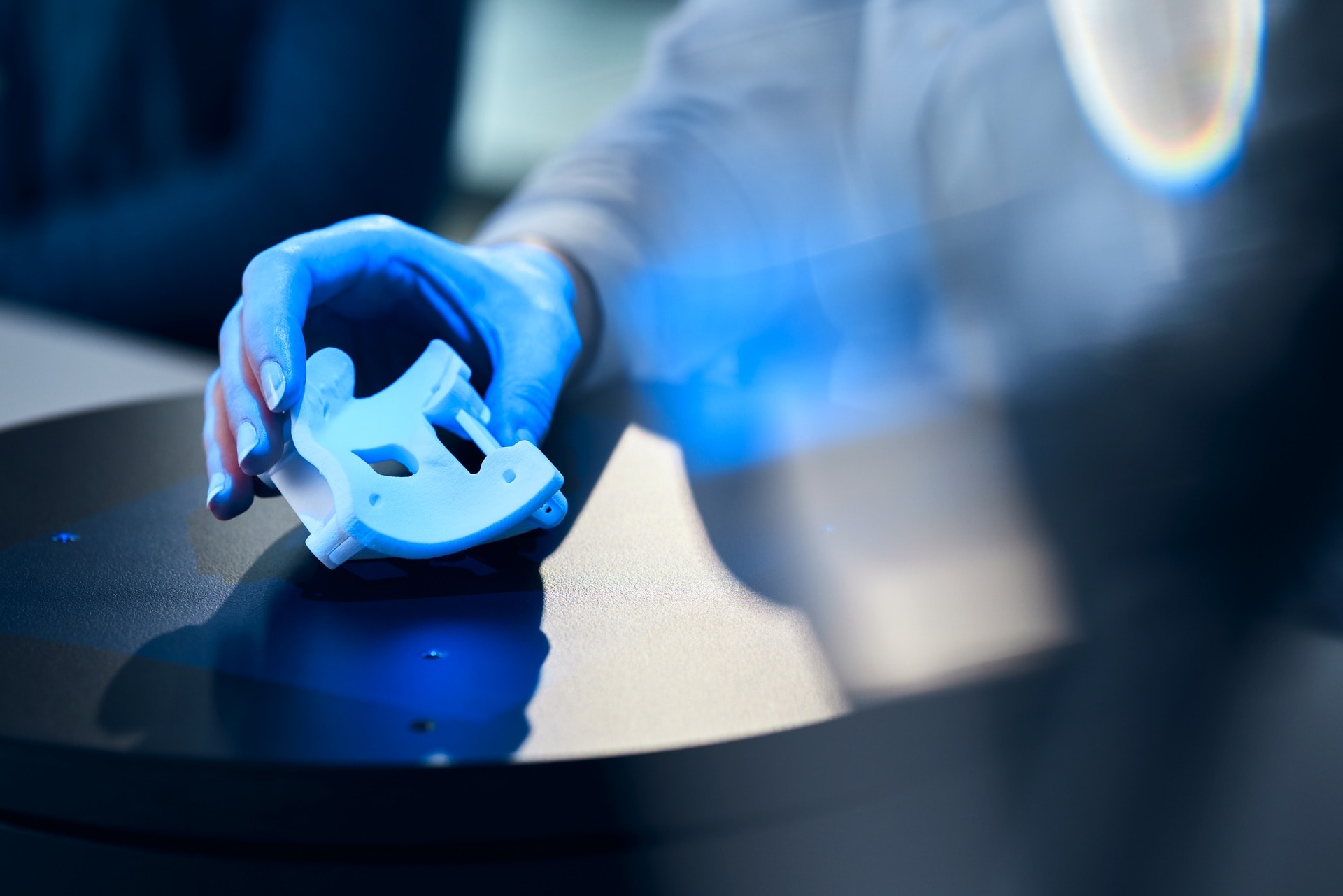
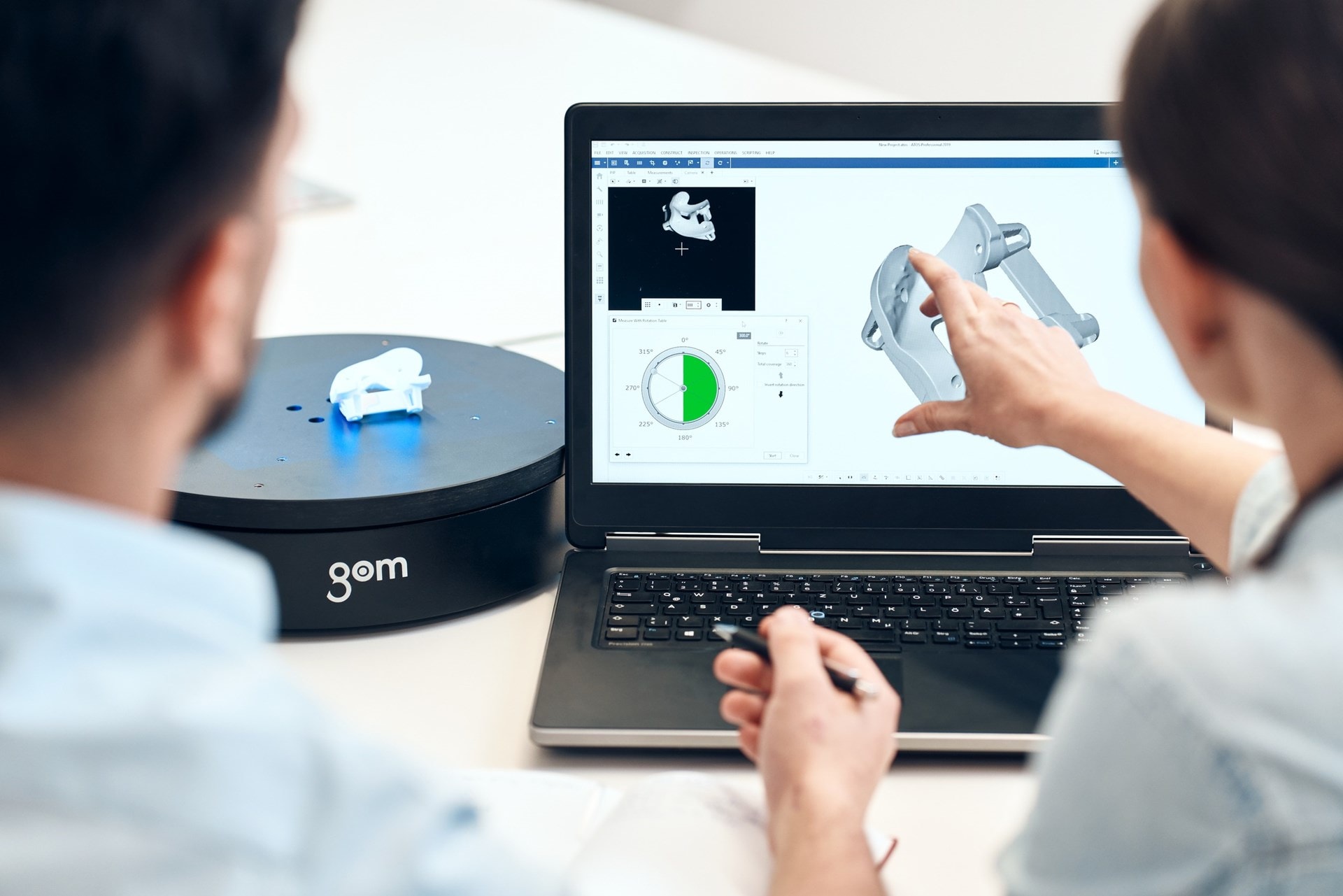
The first step to reconstruct surface data into design data is to use a 3D digitizer of the ATOS series. ATOS digitizers allow for non-contact and full-field scanning of entire part surfaces. Using millions of measuring points, the GOM software computes the 3D coordinates by creating a high-resolution point cloud, the so-called STL mesh.
This polygon mesh forms the basis for creating a CAD model as part of the surface reconstruction. To convert the scan data into mathematically described curves (splines), freeform surfaces (NURBS surfaces), standard geometries (primitives) or solids, the data can be exported from the GOM software as an STL mesh or ASCII point cloud.
The actual conversion of the scan data into a CAD surface model requires specific software packages, such as Geomagic, Tebis and ZEISS REVERSE ENGINEERING. Some CAD programs now also have modules for surface reconstruction.
To ensure that the CAD surfaces actually match the scan data, this newly created surface data can be reimported into the GOM software for validation. The GOM software can then be used to compute the deviations between the new CAD data and the scan model for an accuracy analysis and to visualize them in the form of a color deviation representation.
What potential will reverse engineering have in the future?
It is not always necessary to have the design data available as a CAD model prior to creating a part. Thanks to additive manufacturing methods, reverse engineering is also possible without the work-intensive process of surface reconstruction. So to speak, the part can directly result from the volume model. The STL data generated through 3D scanning is used to reprint parts as a prototype quickly and easily. This procedure is called rapid prototyping.
However, the scan data can also serve as a basis for morphing, where existing CAD models are remodeled according to the scan data in order to modify surface properties or radii, for example. This is another procedure that today works without prior surface reconstruction thanks to software advancements. One important field of application is tool try-out, where morphing helps reduce correction cycles and compensate material behavior such as warpage, shrinkage and springback.
Our customers have already discovered the potential of 3D models for many of their applications. They use digitized models for benchmark and competitor analysis, for example. For this purpose, a competitive part is reproduced according to its 3D scan data, checked and compared. However, the data is also used to create high-quality VR renderings. In this case, entire vehicles or washing machines, for example, are disassembled and each part is scanned separately. All parts are then reassembled in the form of a realistic 3D rendering.
The combination of 3D models with an additive manufacturing process also saves time and material in toolmaking and machine construction and can significantly accelerate the manufacturing process.
The possibilities that high-precision 3D measuring data will offer in the future for reverse engineering, CAD or mesh morphing, additive manufacturing and virtual reality applications are by far not exploited yet. What we need are creative engineers, intelligent software and powerful hardware to discover new fields of application.


