ARGUS
Evaluation of Forming Processes and Simulation Validation
The optimization of the sheet metal forming process, taking into account the correct material selection and optimization of tools, is a decisive factor for competitiveness, particularly in the automotive industry during the development process of sheet metal parts, for tool try-out and in production troubleshooting. The forming analysis system ARGUS supports such optimization processes particularly by convincing and precise results of the surface strain on the components. The full-field results with high local image resolution provided by ARGUS enable the measurement of small and large components.
Applications
- Tool try-out
- Validation and optimization of numerical simulations
- Series production ramp-up
- Material acceptance test (material batches)
- Research and development
- Detection of critical deformation areas
- Solving complex forming problems

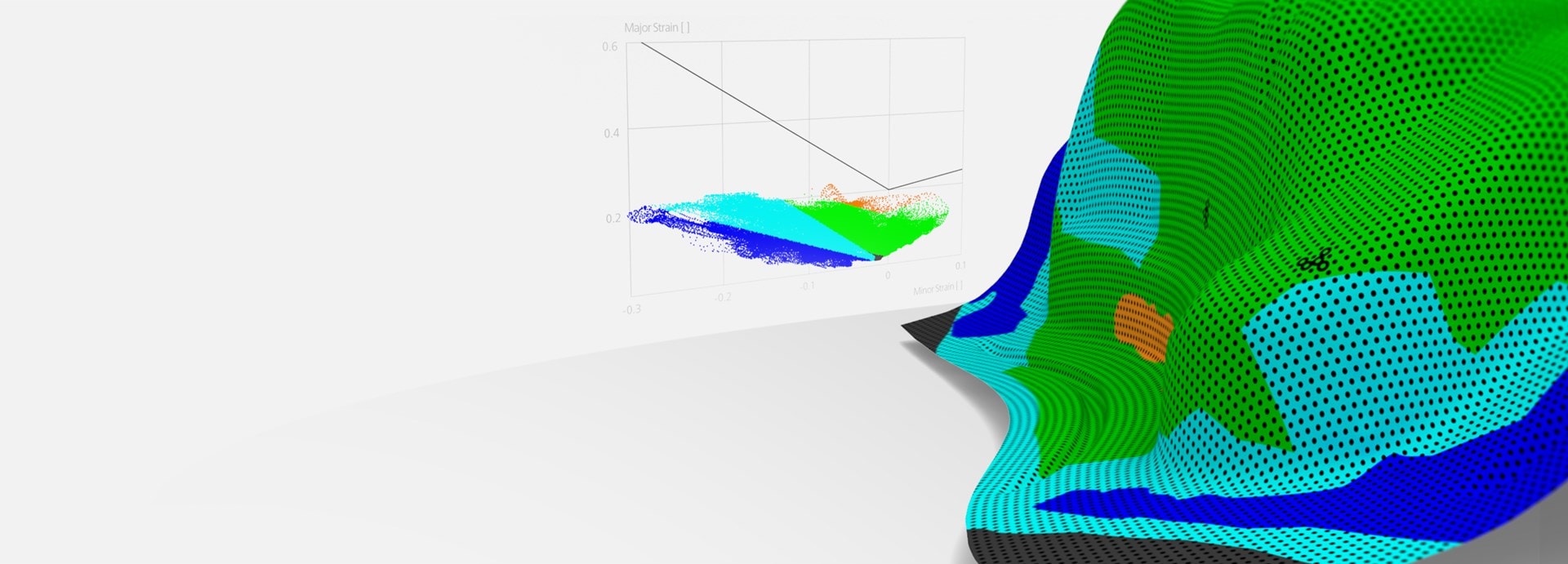
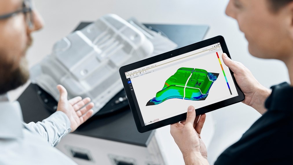
Forming Analysis
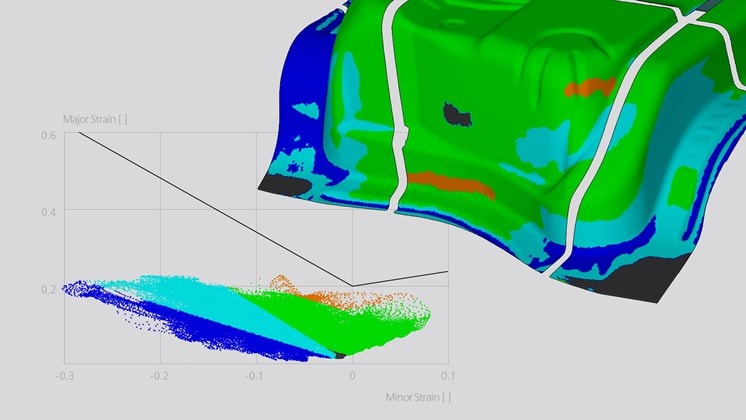
Forming analysis is a process to evaluate the forming states and surface strain levels of sheet metal parts after forming. GOM’s ARGUS system can be used to capture 3D coordinates of the surface presented in a fine resolution mesh. The forming results are subsequently compared with the Forming Limit Curve (FLC), a material parameter dataset describing the maximum formability, by means of a Forming Limit Diagram (FLD) that is created in the GOM Correlate Pro. This diagram clearly indicates whether the areas are over-deformed or still within a certain safety margin, providing decisive information for optimizing forming processes and validating simulations.
GOM Correlate Pro Software
Based on the measuring data acquired by the ARGUS photogrammetry camera, the GOM Correlate Pro provides a fast and efficient evaluation workflow for forming analysis.
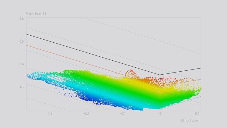
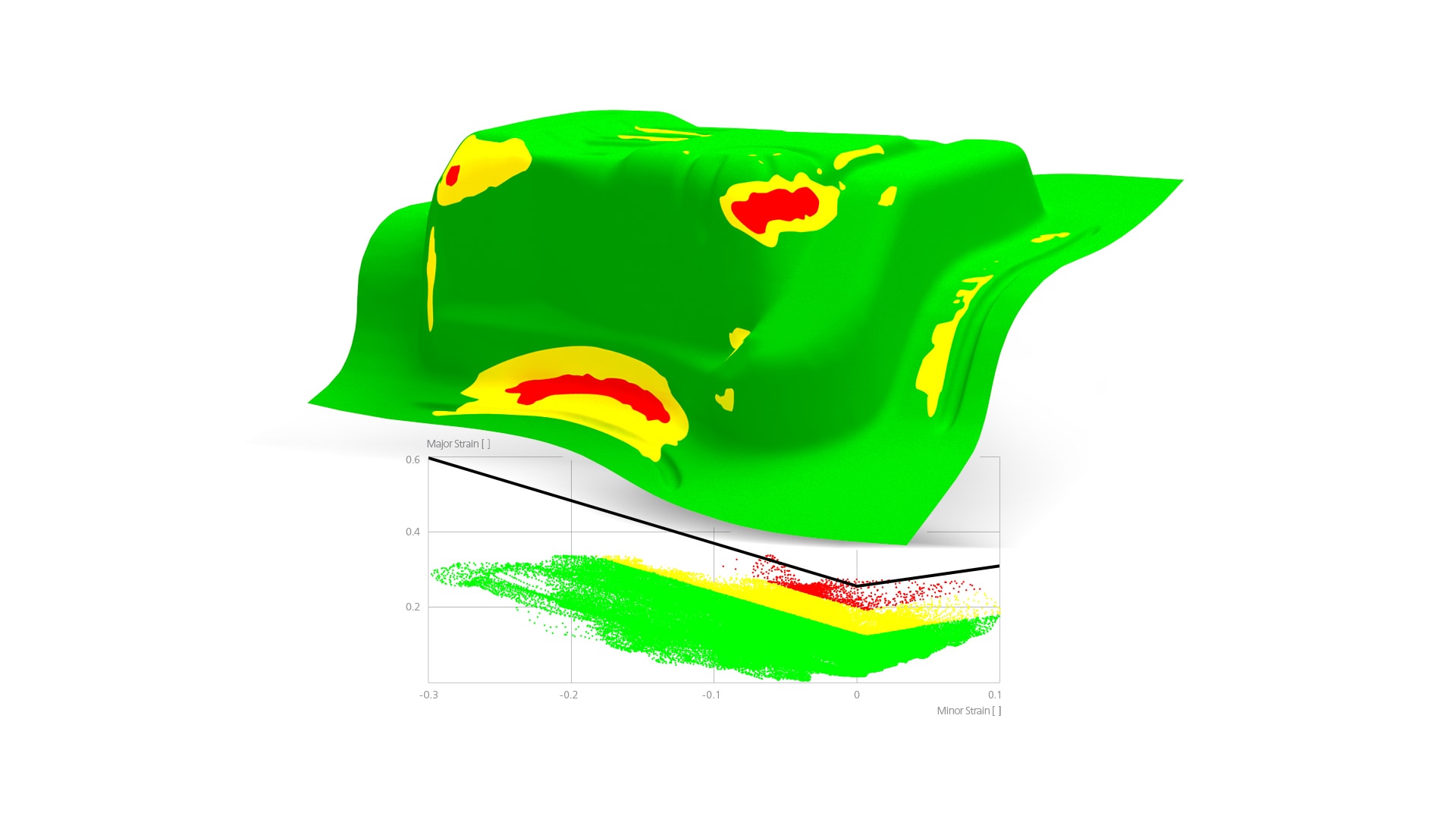
FLD/ FLC
The Forming Limit Diagram (FLD) is a proven tool to evaluate the forming process and determine the trend towards cracking. In the GOM Correlate Pro software, the FLD can be easily created with one click in I-Inspect. Besides the Forming Limit Curve, additional curves such as the Security Curve, Thickness Reduction Curve, Isotropic Tension Curve, can all be visualized in the software. Furthermore, multiple Forming Limit Curves (FLC) can be created by simply importing the ARAMIS material file or calculated directly in the GOM Correlate Pro software by Keeler for further analysis.
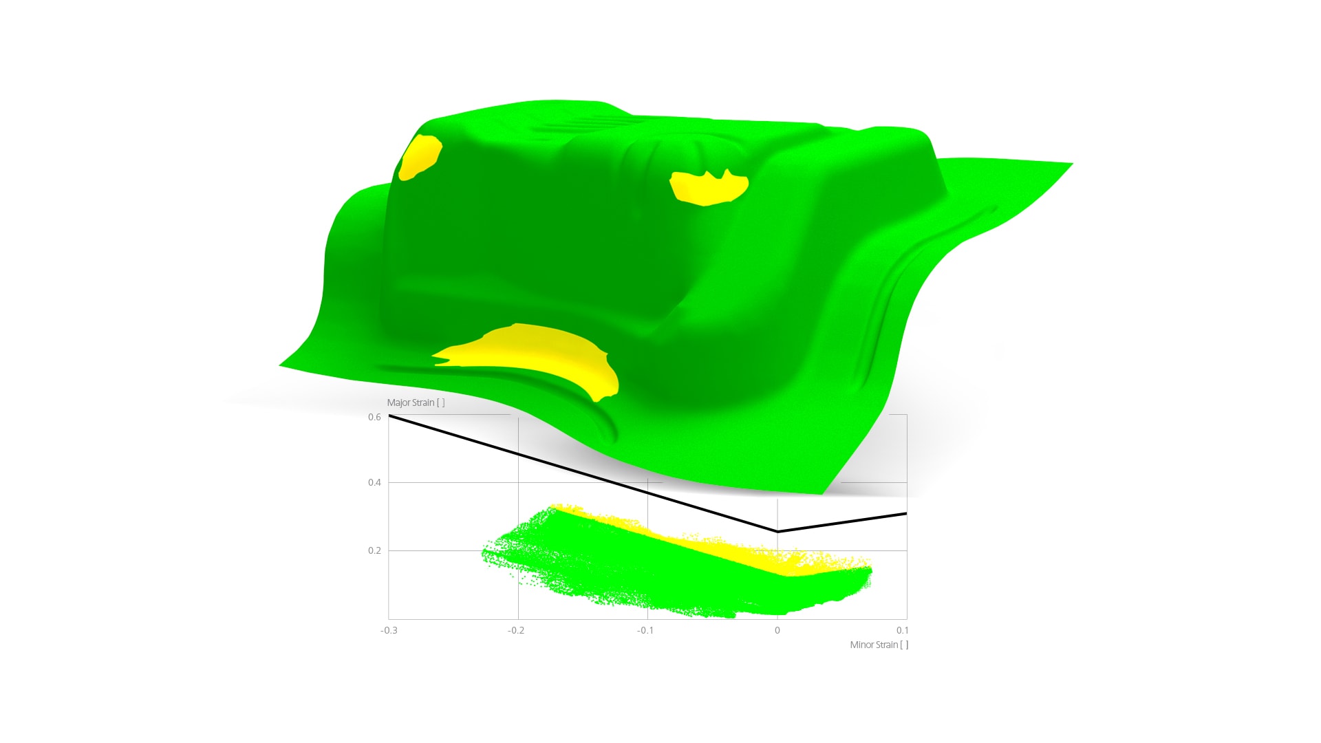
Formability
Formability analysis takes one step further. Like in many simulation programs, such as AutoForm, this formability diagram can also be created by one click in the GOM software. The user can define different classification areas and visualize them directly in the Formability Diagram and on the specimen for further inspections.
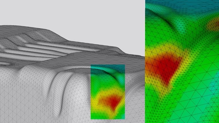
Simulation
Scalar values and geometries from simulation programs such as ABAQUS, LS-DYNA or ANSYS, for example, can be imported into the GOM software for a direct comparison to the 3D measuring data. The 3D measuring data can be transformed into the coordinate system of the simulation model by various alignment functions. Thus, the geometry of the simulation model can be compared with the measured 3D surface in a first step. Further analyses, such as the direct comparison of displacements, deformations and strain, can be carried out for each stage.
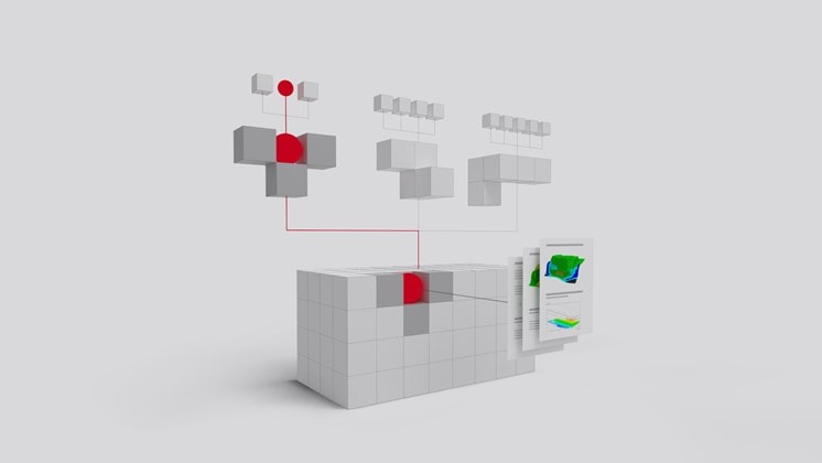
Parametric project templates
The GOM software is based on a parametric concept. This approach ensures that all process steps are traceable, thus guaranteeing process reliability for measuring results and reports. In the evaluation process, all steps, including the creation of alignments (for example by CAD), inspection elements and the complete user-defined reports are documented and can be saved as project templates. Further projects of the same type can be easily repeated by simply changing the measuring data and recalculating the project. This project template can be stored and exchanged between colleagues, departments or even plants worldwide, which guarantees uniform evaluation standards for your projects.
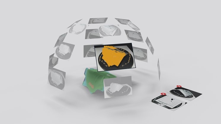
Guided data acquisition
A successful evaluation requires high-quality measuring data. The active guidance of the GOM software provides a direct feedback on the image quality during the image capturing process. Images are automatically considered usable or unusable and displayed clearly in the software. Users can react to the messages shown by those unusable images to adjust the position, change the luminous intensity, for example, or just give a second try. With the new image mapping functionality, the measuring positions are displayed around the object, which makes the missing measuring positions directly visible.

Automated mesh generation
Fewer user interactions are now needed to obtain results. The automated starting point allows automatic identification and computation of 3D meshes of single or multiple measuring areas. These meshes can be created independently of the user, which increases the repeatability of the measuring results.
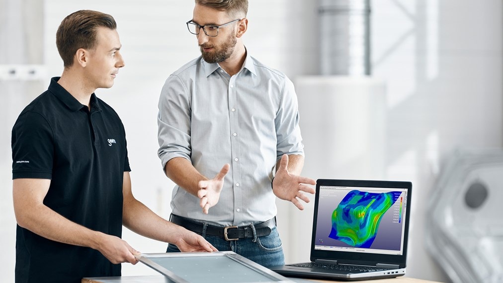
GOM Correlate Software
The measuring data taken from the ARGUS system can be easily viewed and evaluated using the free GOM Correlate software. Besides that, the software supports the free exchange of measuring results between colleagues, across departments and plants worldwide for further analysis.

Easy and Fast Measurement
Different from conventional methods for forming analysis, the ARGUS system provides an easy and fast measuring process as well as accurate forming results. Even complex and large parts can be measured within a short period of time.
Measurement Planning
Before preparing the part, the measuring areas need to be defined depending on the evaluation purpose, which may be the complete part or specific critical areas known from the production process or numerical simulation.
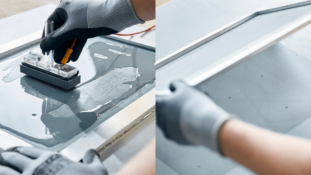
Preparing
Before forming, raw sheet metal blanks are marked using electro-chemical etching or laser marking with a hexagonal dot pattern.
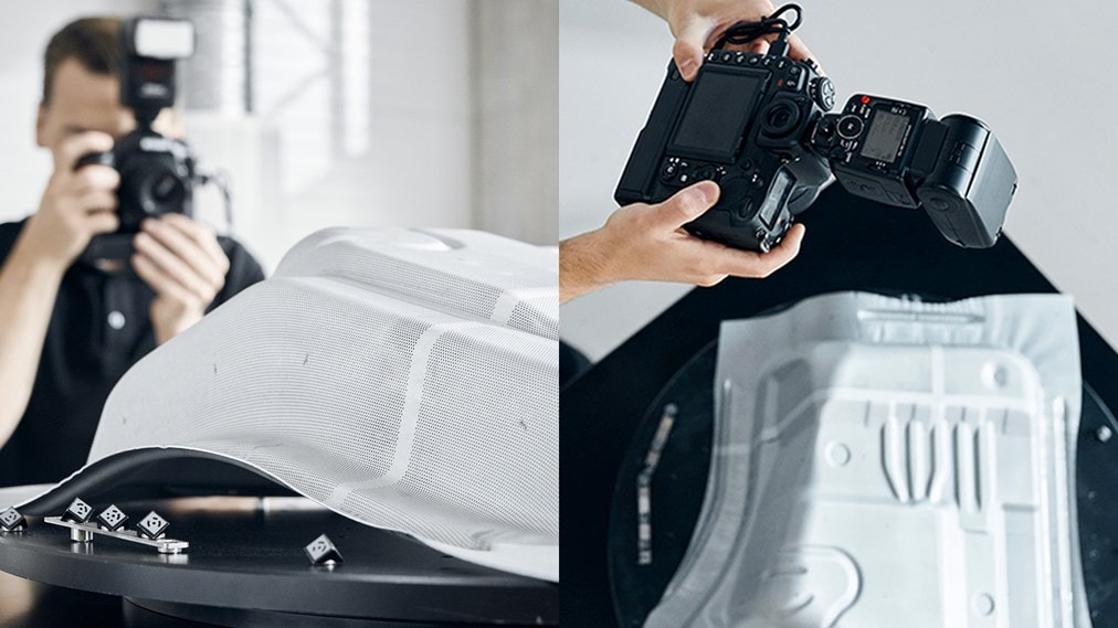
Measuring
After forming, the sheet metal part is recorded from different viewing angles by using the handheld ARGUS system. Small and large parts can be measured very fast with the same hardware.
Evaluation
Measuring results provide full-field information of the forming distributions on the parts, like major and minor strain, thickness reduction, forming limits, formability etc.

Services
GOM keeps supporting its customers after the purchase and installation of 3D measuring systems.

