Material testing and component testing
Material testing and component testing
Material testing and component testing are two fields in the world of mechanical, thermal or chemical testing. During material testing, the behavior and material parameters of material samples are determined. During component testing, the behavior of finished components under thermal, chemical or mechanical stress is examined accordingly.
In this post you will learn:
- Which methods are used in material and component testing
- What is the difference between a material test and a component test
- What camera-based measurements can do
- How cyclic tests are carried out as realistically as possible
- What modern procedures for testing look like
- What size a specimen or component must have for the test
The methods of material and component testing
In principle, a distinction is made between two main areas, both in materials testing and in component testing: Destructive material and component testing as well as Non-destructive material and component testing.
Non-destructive material and component testing
Non-destructive testing, or NDT, enables the quality of a workpiece to be tested without having to destroy the test object used. We have detailed the exact process of non-destructive testing, the advantages and areas of application in a separate article.
Destructive material and component testing
In destructive testing, materials and components are tested for their physical and/or chemical properties and changed or destroyed during the testing process. The component that is examined by means of a destructive test can then no longer be used. Destructive testing can be divided into two main groups:
- Mechanical testing
- Chemical/thermal testing
Destructive, mechanical testing
In mechanical testing, materials and components to be tested are exposed to different mechanical loads. Common mechanical test methods include:
- Tensile tests to determine tensile strength and other material parameters
- Burst tests to test the strength of containers, boilers or pipelines
- Nakajima test series to determine the forming limit curve of sheet metal materials
- Bulge test or hydraulic deep drawing test to determine the biaxial yield curve of sheet metal materials
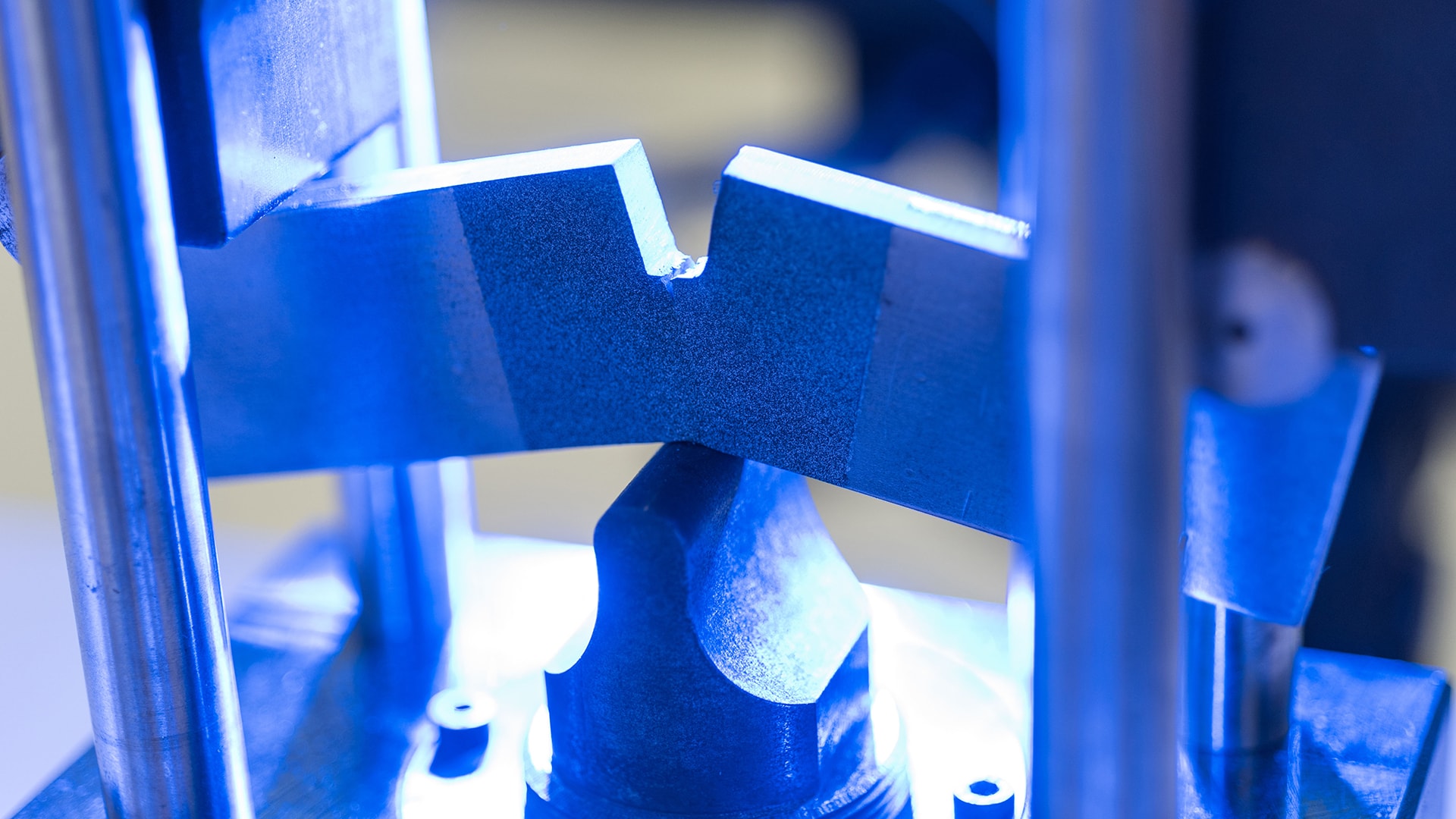
- Bending tests to test sheet metal
- Pressure tests
- Torsion tests
- Shear tests
- Pull-out tests
Destructive, thermal or chemical testing
In thermal testing, materials or components are exposed to high temperatures, cold temperatures or changing temperature conditions. In chemical testing, one examines the molecular behavior of materials. Common methods in thermal/chemical testing include:
- Firing samples
- Forehead quench tests
- Differential thermal analyses
- Gas chromatography
- Metallography
- Crystallography
What is the difference between a material and a component test?
A material test takes a close look at the respective material - i.e. the material from which a future workpiece is to be manufactured. During a material test, the material to be tested is examined for its quality and behavior in response to among others mechanical loads, environmental and chemical influences. Typical quality defects that are uncovered during a material test are density differences, structural defects, voids or hairline cracks.
A component test, on the other hand, is used to check a manufactured workpiece for its functionality. The components are tested, among other things, for their safety in use, for strength or deformability, and for toughness and fatigue properties.
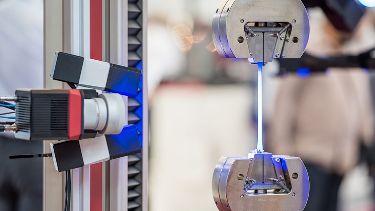
What can camera-based measurements do in material and component testing?
With advancing digitization, camera-based measurements in non-destructive and destructive testing are increasingly moving into focus. In particular, high flexibility in the area of optical expansion and the associated optimal adaptation to the respective test process characterize optical measurement using cameras. Cameras (and of course a corresponding measurement software in the background) allow the expansion and deformation behavior of any components to be tested and the areal measurement of 3D coordinates, 3D displacements, velocities and accelerations as well as surface strains.
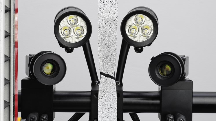
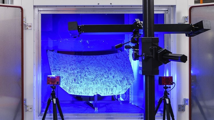
How camera-based measurement works
The component or material sample to be tested is clamped in a test device. One or more digital cameras (depending on the test method and purpose) then record the deformation process or movement in 3D space. The surface of the component must be prepared with a stochastic high contrast pattern, the so-called speckle pattern, or must be prepared with circular measuring markers for an analysis of motion and/or deformation in 3D space. This pattern is either naturally present or is applied to the component before the test. The images that the camera takes are automatically evaluated by the software. The resulting data is also visualized automatically.
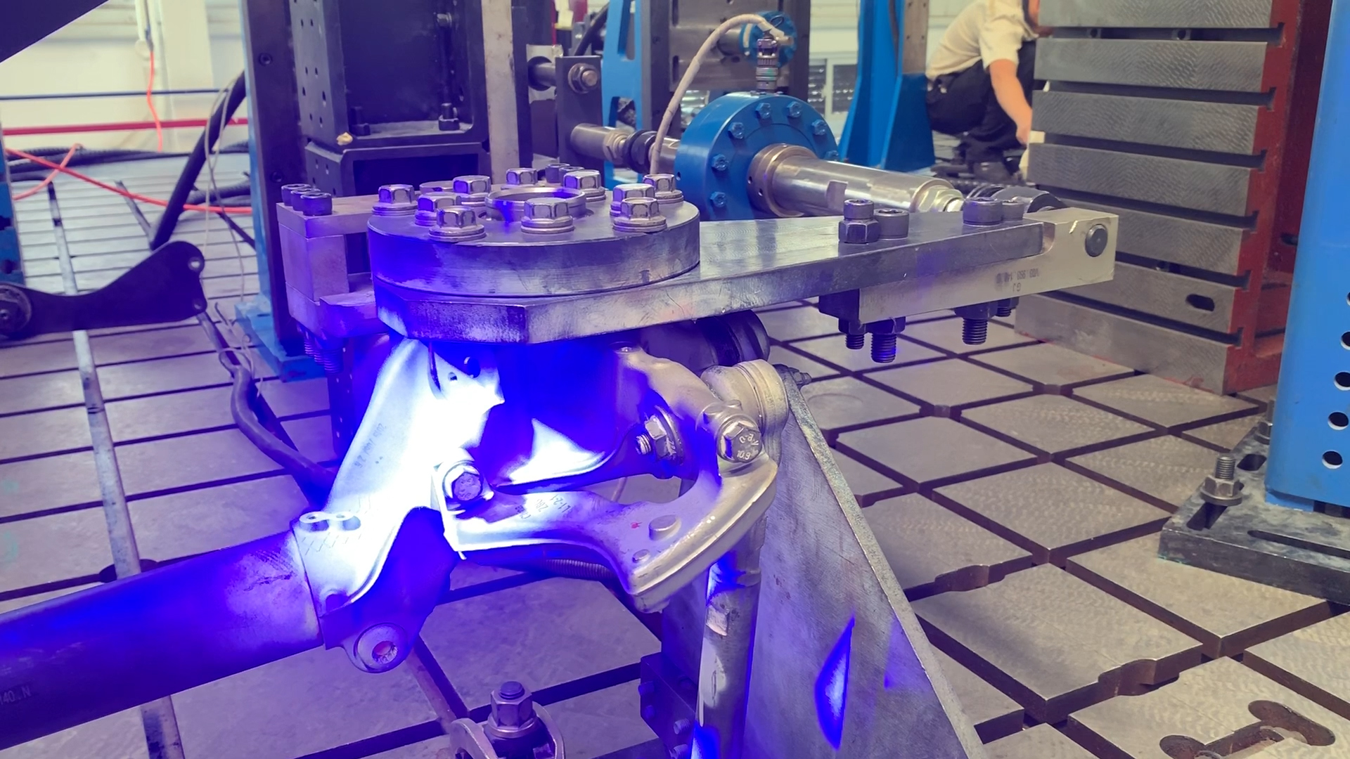
How are cyclical tests of materials and components carried out as realistically as possible?
If components are regularly dynamically loaded, the material structure inevitably changes in the course of use. The material loses its ability to respond elastically and thus reversibly to the stresses in use. In the further course of the process, the material becomes fatigued until it finally breaks. A cyclical test of the material properties, meaning that it is repeated regularly in a defined period of time, is used in the design phase to optimize the selection of a material based on the dynamic loads to be expected during operation. With this knowledge, components can be dimensioned optimally.
However, dynamic testing under laboratory conditions does not correspond to the stresses to which a component is exposed in reality. This is because regularly recurring load processes, as are common in cyclical testing, are difficult to distribute with the load levels and load sequences that are stochastically distributed over time and that act on components in reality. The comparison between the standardized test specimens in materials testing and the components in "real" use cannot be made without compromises. Surface influences, material defects, technical notches or corrosion have an impact on components in daily use - on the other hand, these influences are absent in standardized test samples.
This problem is usually countered with a practical component test. This requires an extremely high number of components that are subjected to a test - which requires a correspondingly high use of test equipment, test personnel and, last but not least, capital. Even if more and more digital simulations are used, they cannot completely solve the problem.
One approach to a cyclical test that is as realistic as possible is to subject components with defined previous damage to a test. For this purpose, the worst of all possible components is produced and then tested. If this component still offers sufficient safety in use, a reliable assessment of its safety can be carried out on the basis of just one test.
If you want to learn more about cyclic tests in mechanical material and component testing, take a look at the article on fatigue tests.
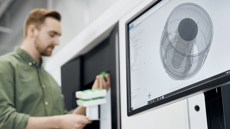
What do modern methods for material and component testing look like?
Thanks to a high level of automation, modern material and component testing is increasingly approaching the ideal of seamless, comprehensive testing. Optical methods such as computed tomography, an X-ray method, are particularly suitable here. On the one hand, the required test systems can be integrated into a production line, and on the other, internal defects and geometries can also be reliably tested. The digital detectors currently in use allow data to be generated in real time and evaluated automatically. In industry, in particular, extremely large amounts of data are generated during a test process, which humans can barely evaluate, or not at all. AI (Artificial Intelligence) is therefore increasingly being used. AI makes software "capable of learning": The more components or materials the AI analyzes, the more precisely the subsequent assessment is carried out with regard to error tolerances. Computed tomography in component testing has another major advantage: It not only makes it possible to measure components three-dimensionally, but also to reconstruct the components in a digital environment. This creates a "digital twin” to carry out a real-time test within the production line.
What size does the component or sample have to be?
Typically, test samples for mechanical material tests are standardized with regards to their geometry and size in norm documents. To ensure that material parameters that have been determined under standardized conditions can be transferred to the actual test process, different size influences must be taken into account when designing the component or the sample. The following are relevant regarding the influences of size:
- Geometric influence of size
- Statistical influence of size
- Technological influence of size
- Surface influence of size
Corresponding correction factors must be taken into account in the design so that a component test does not output incorrect values. Alternatively, a lower limit value can also be determined, because the statistical influence of size increases with the increasing probability of breakage. On the so-called zero break line, the influence of size disappears when the probability is zero.
When it comes to samples, size also plays a key role. The smaller a sample is, the more the material behavior changes in the direction of the behavior of individual atoms or molecules. In some cases, this effect has a strong influence on constants such as the melting temperature or the specific resistance.


